Fig. 3
Complete
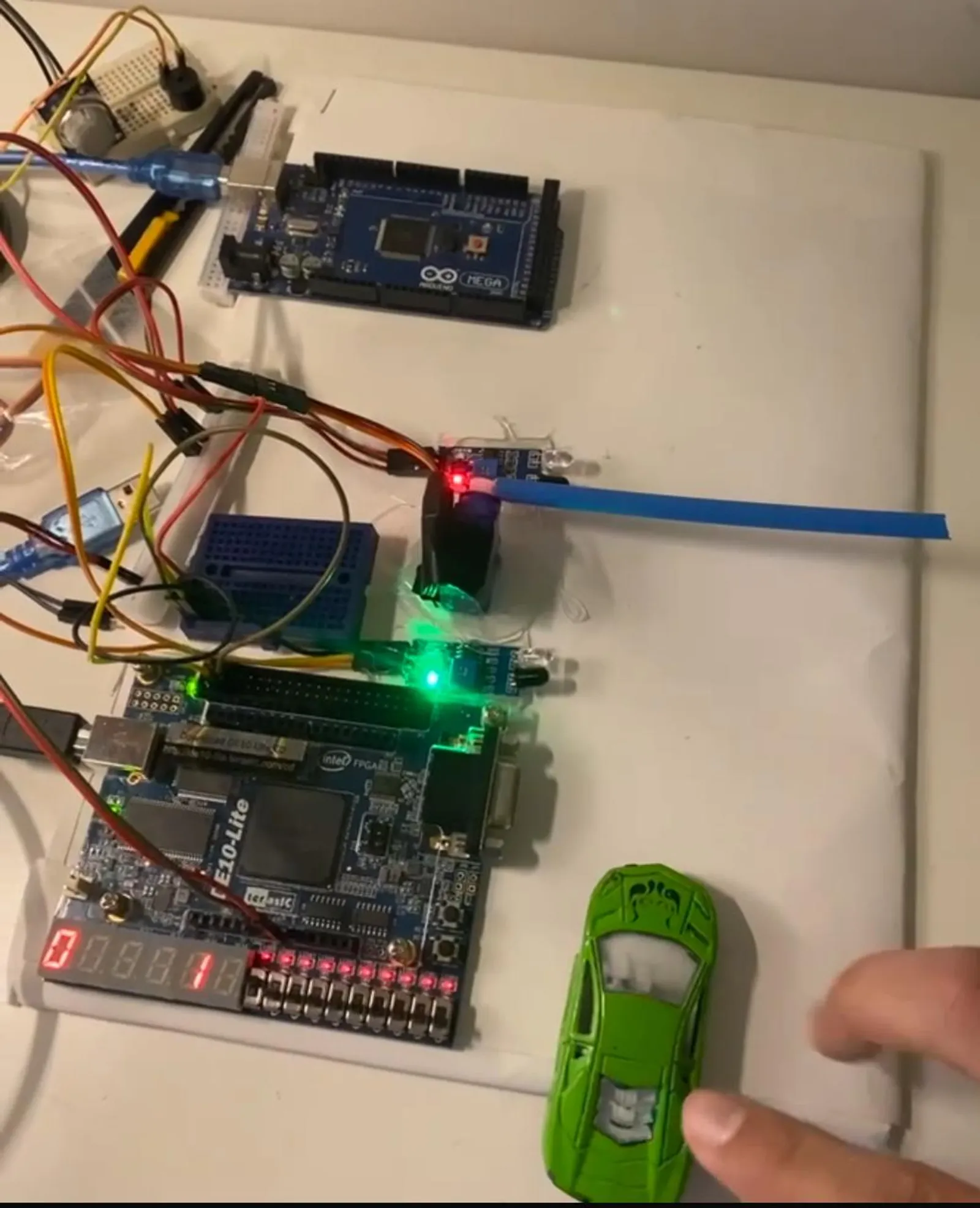
Smart Parking System
An eight-spot garage run by an FPGA, with an Arduino watching for fire
A gate controller for a small garage, built on a DE10-Lite FPGA. A VHDL state machine reads two IR sensors to tell a car entering from one leaving, debounces them, and keeps the count of free spots — eight at most — on a 7-segment display. An Arduino Mega reads an MQ-2 smoke sensor and, above a threshold, forces the gate open and sounds a buzzer, overriding whatever the state machine is doing. A voltage divider steps the Arduino's 5 V signal down to the FPGA's 3.3 V.
Procedure
4 min
What it does
A garage with eight spots, one gate, and a servo to lift it. Two infrared sensors sit on either side of the gate — one outside, one inside. From the order in which they trip, the system knows whether a car is coming in or going out, opens the gate for exactly as long as the car needs, and keeps a running count of free spots on a 7-segment display. When the garage is full, the gate stays down.
The whole thing runs on a DE10-Lite board with an Intel MAX 10 FPGA, written in VHDL. An Arduino Mega sits beside it doing one job: watching for smoke.
Two sensors, one state machine
The gate logic is a finite state machine that reads the pair of sensors as a two-bit value — outer, inner. The trick is that a car crossing the gate always trips the sensors in sequence, so the sequence tells the direction.
| State | What it is waiting for | What it does |
|---|---|---|
| Waiting | The outer sensor to trip | Keeps the gate closed |
| Entering | The car to clear the inner sensor | Gate open; counts one spot down when the car is fully through |
| Exiting | The car to clear the outer sensor | Gate open; counts one spot up when the car is fully through |
| Wait for clear | Both sensors to read clear | Holds the gate open so it cannot drop on a car |
The count only changes once a sequence completes. A car that pokes past the outer sensor and reverses out never touches the counter, and neither does a hand waved in front of one sensor. The “wait for clear” state is the safety net: whatever else is happening, if either sensor sees something, the gate stays up.
Infrared sensors are noisy — a passing car produces a burst of on-off flicker rather than a clean edge. A debouncing stage in VHDL ignores anything shorter than a set number of clock cycles, so the state machine sees one clean transition per event.
Manual control
A push button on the board opens the gate by hand. Two rules apply. The button goes through a 50 ms debouncer, so one press is one press. And the button is ignored when the count reads zero: a full garage cannot be opened manually, only exited.
When there is smoke
The MQ-2 sensor is an analogue gas sensor, and the FPGA board has no analogue inputs, so the Arduino reads it. When the reading crosses 300 the Arduino raises a single digital line to the FPGA.
On the FPGA that line outranks everything. Whatever state the machine is in, the gate opens and a buzzer sounds. The count is left alone; the point is to get cars out, not to keep score. The Arduino holds the line high for at least three seconds after the last reading over threshold, so a flickering sensor cannot make the gate stutter.
Two voltages on one wire
The Arduino runs its logic at 5 V. The FPGA’s general-purpose pins are rated for 3.3 V, and driving them at 5 V would damage them over time. The smoke line therefore passes through a voltage divider — 10 kΩ and 20 kΩ — that turns the Arduino’s 5 V high into roughly 3.3 V before it reaches the FPGA.
In the box
The gate is an SG90 servo; the sensors are two IR obstacle modules and one MQ-2. The VHDL is split into the main control file, with the state machine, debouncer, and counter, and a small 7-segment driver that only needs to show zero through eight. The repository has the sources, the pin assignments for the DE10-Lite, the full report, and two videos — one of the system running, one of the simulation waveforms.